Tutorial
In about 10 minutes, you import a topology, arrange it, add a workstation, fix a warning, and publish a topology and an experiment. The example is Riverside Water, a small water utility with an internet edge, a DMZ, a corporate network and an OT network behind a firewall.
The example lab
You need a phēnix server, and a role that can use Builder, such as Global Admin or Builder (see Administration).
Download these files:
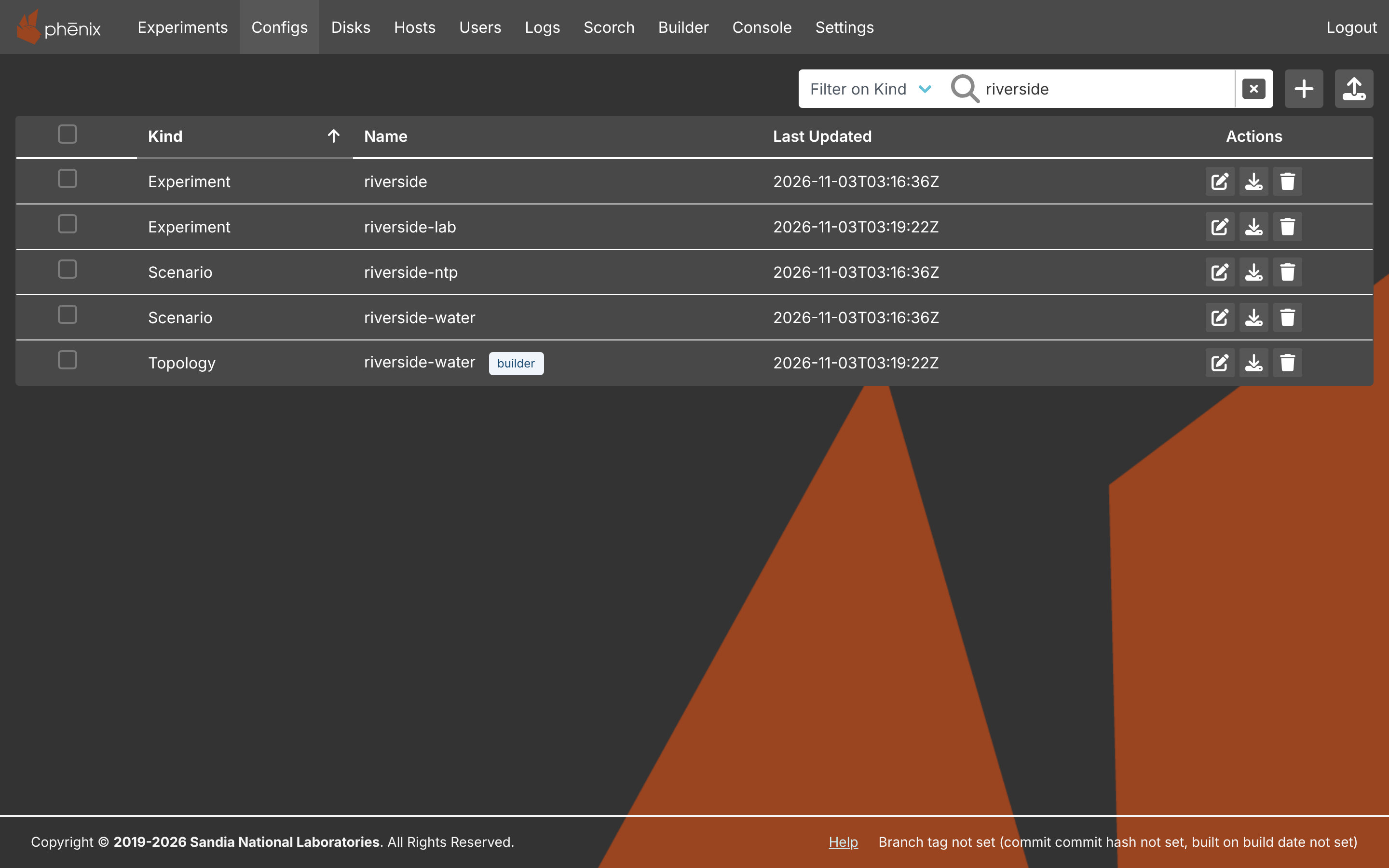
Store the three configs, and create the experiment riverside from them.
From the command line:
phenix config create corp-services.topology.yaml riverside-water.topology.yaml riverside-water.scenario.yaml
phenix experiment create riverside -t riverside-water -s riverside-water
Or use the Web-UI. Upload the three configs on the Configs page (see
Create a Config). Then create the
experiment riverside on the Experiments page, with the topology and
the scenario riverside-water (see
Create a New Experiment).
The other pages use more example files: pump-station.topology.yaml, pump-station.builder.json, pump-station.package.yaml, riverside-water.builder.json, lakeside-treatment.builder.json and node-templates.yaml. You do not need them now.
Step 1: Import the topology
- Click Builder in the navigation bar. The drafts page opens.
- Click Import.
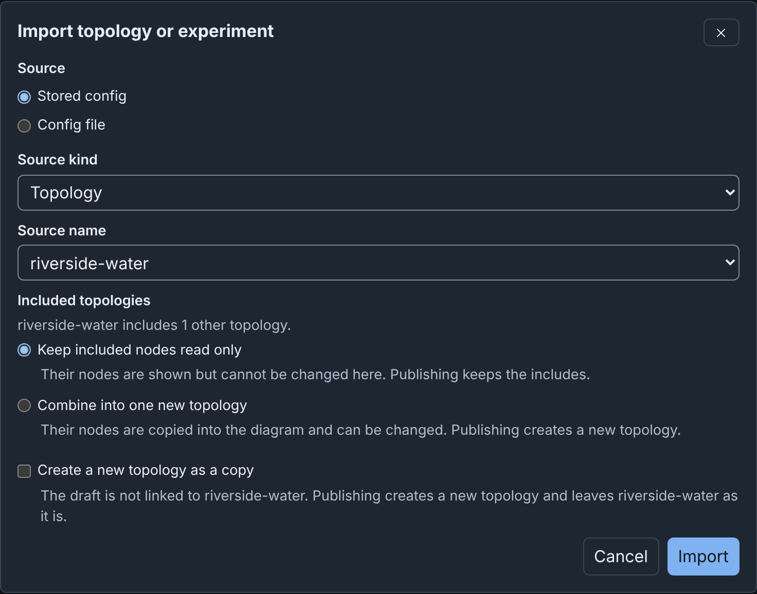
- In the Import topology or experiment dialog, select
riverside-waterunder Source name. Keep the other fields as they are. - Click Import. The dialog says "This import has 1 warning." The
warning says that
dns-01andntp-01come from the included topologycorp-servicesand are read only. - Click Continue to editor.
A new draft named riverside-water opens in the editor, with its devices
in rows on a grid. Builder saves every change that you make from now on.
The toolbar shows the save state, for example All changes saved.
Step 2: Arrange the diagram
- In the toolbar, open the layout menu. It says Default.
- Select ELK layered. Each switch moves next to its devices.
- Click Auto-group. Select By network. Builder puts each network in a group: CORP, DMZ, INTERNET and OT.
- Click Fit diagram to view at the bottom left of the canvas.
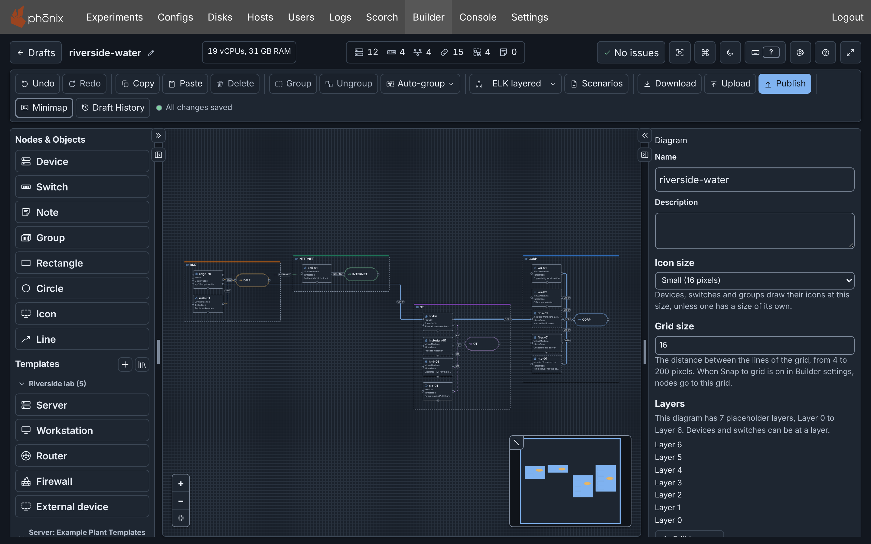
The two devices with a dashed border, dns-01 and ntp-01, come from the
included topology corp-services. You can move them, but you cannot change
them here.
Step 3: Add a workstation
- Under Templates in the left column, click Workstation. A device
named
workstationappears on the canvas, and the Inspector on the right shows its settings. - In the Inspector, set Hostname to
ws-03and Description toEngineering workstation. - Under Network, click Add interface. The new interface is
eth0, with Interface kind Static or OSPF and Mask24. - Enter Address
10.10.20.103, Gateway10.10.20.1and VLANCORP. - Click Apply.
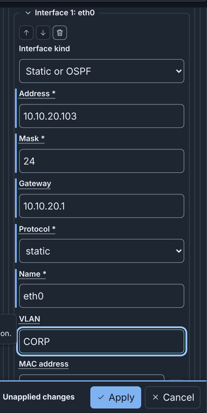
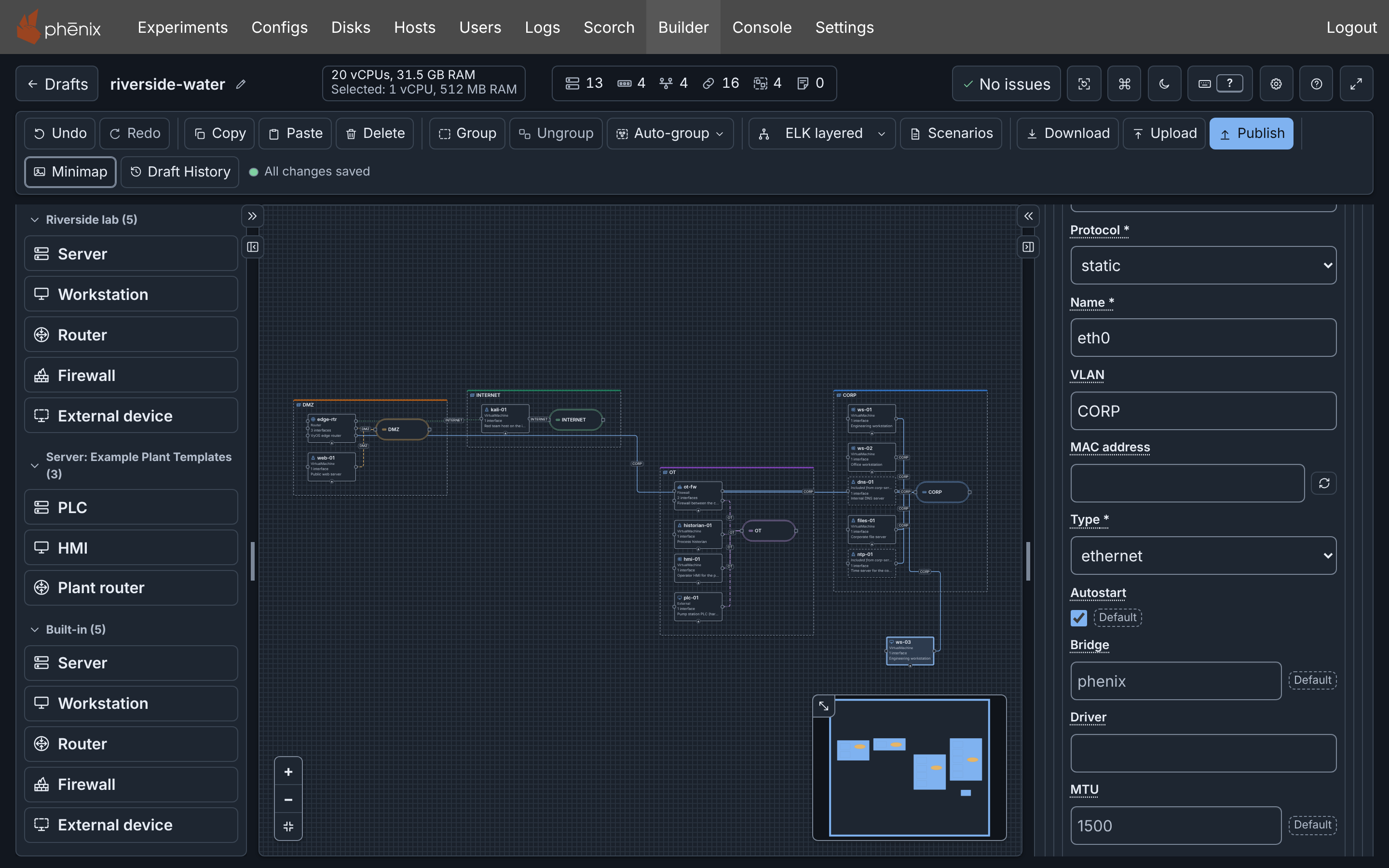
Builder connects eth0 to the CORP switch, because the VLAN names that
network. The header now counts 13 devices and 16 connections, and says
No issues. On a server that lists its disk images, the header can
also show a warning for an image that the server does not have. That
warning does not block publishing (see The Editor).
Tip
You can also connect a device with the mouse. Drag from the + handle under the device to a switch. Builder adds the interface and, when the network has a subnet, gives it the next free address.
Step 4: Fix a warning
Builder checks the diagram while you work. To see a warning:
- Select
historian-01on the canvas. - Press Ctrl+D (⌘+D on macOS).
A copy named
historian-01-2appears, with an interface that is not connected. The header says 1 warning. - Click 1 warning. The Diagram checks dialog says that
eth0ofhistorian-01-2has no VLAN. - Click Go to beside the warning. The canvas selects the copy.
- Click Delete in the toolbar. The header says No issues again.
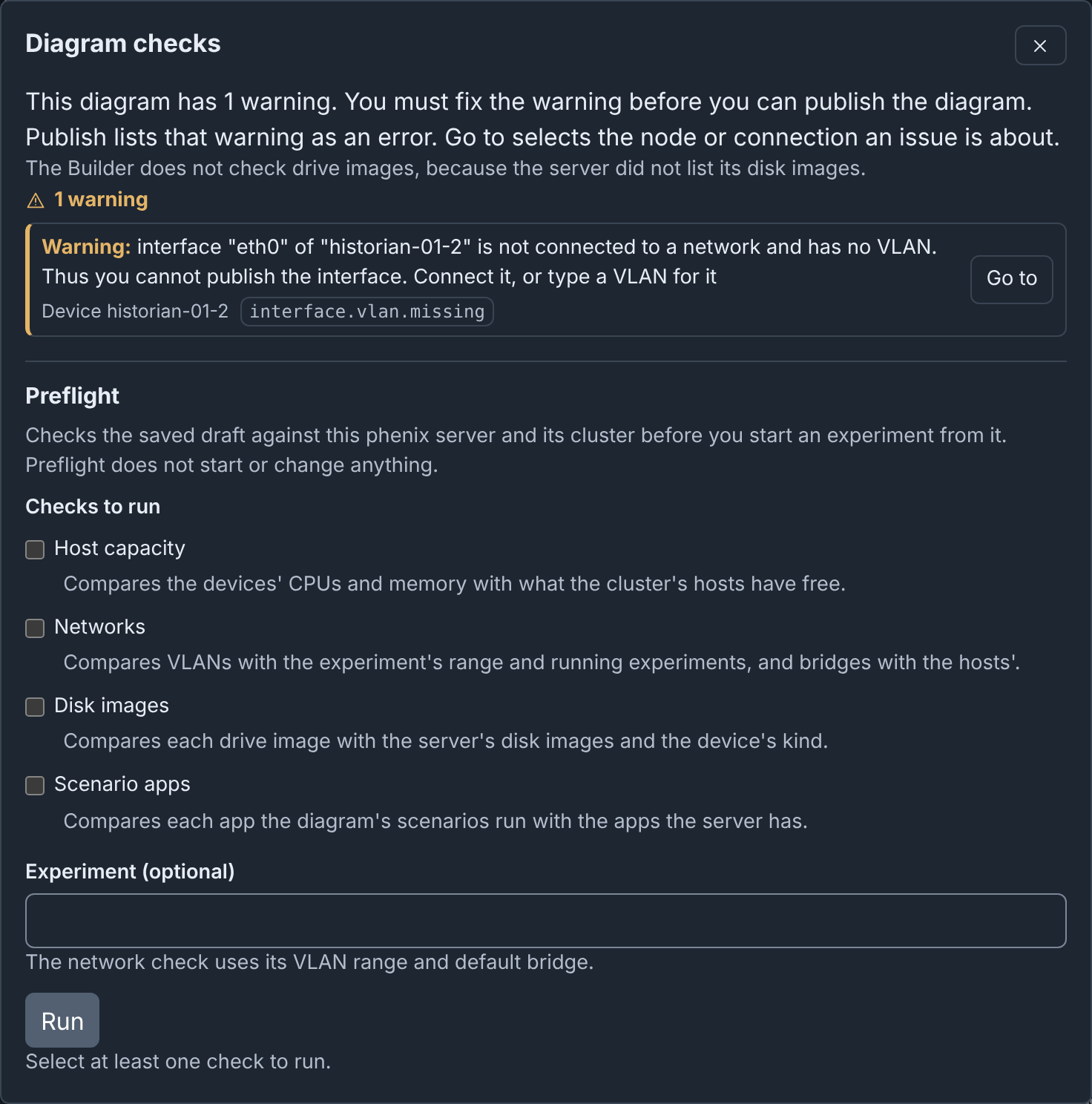
A warning like this blocks publishing, because the experiment would fail or operate incorrectly with it. Other warnings only inform you. See The Editor.
Step 5: Add the scenario
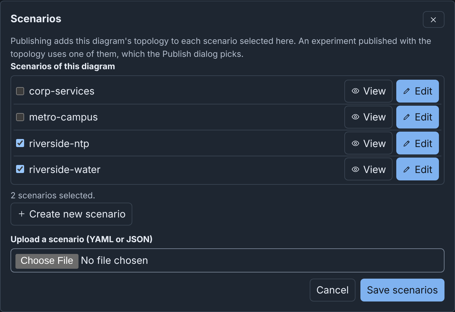
To give the experiment a scenario, add it to the diagram. The diagram lists the scenarios that it uses:
- Click Scenarios in the toolbar.
- Under Scenarios of this diagram, select the checkbox of
riverside-water. - Click Save scenarios.
Step 6: Publish
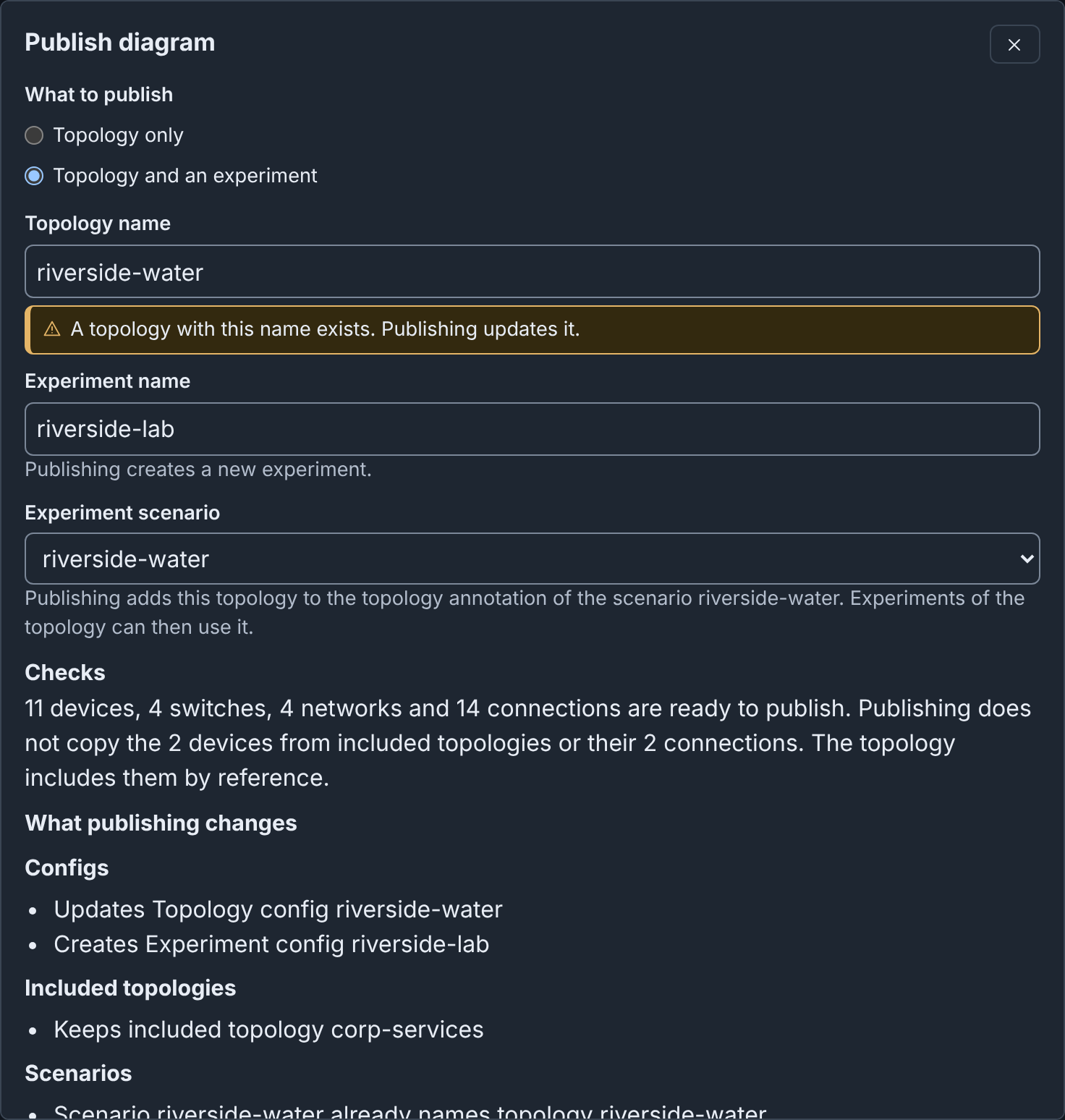
- Click Publish in the toolbar. The Publish diagram dialog opens.
- Under What to publish, select Topology and an experiment.
- Keep Topology name
riverside-water. The hint says "A topology with this name exists. Publishing updates it." - Enter Experiment name
riverside-lab. - Keep Experiment scenario
riverside-water. - Read Checks. It says that 11 devices, 4 switches, 4 networks and 14
connections are ready to publish. Publish does not copy the two
included devices: the topology includes
corp-servicesby reference. - Click Update topology and create experiment. Builder asks "Replace topology riverside-water?".
- Click Update topology and create experiment again.
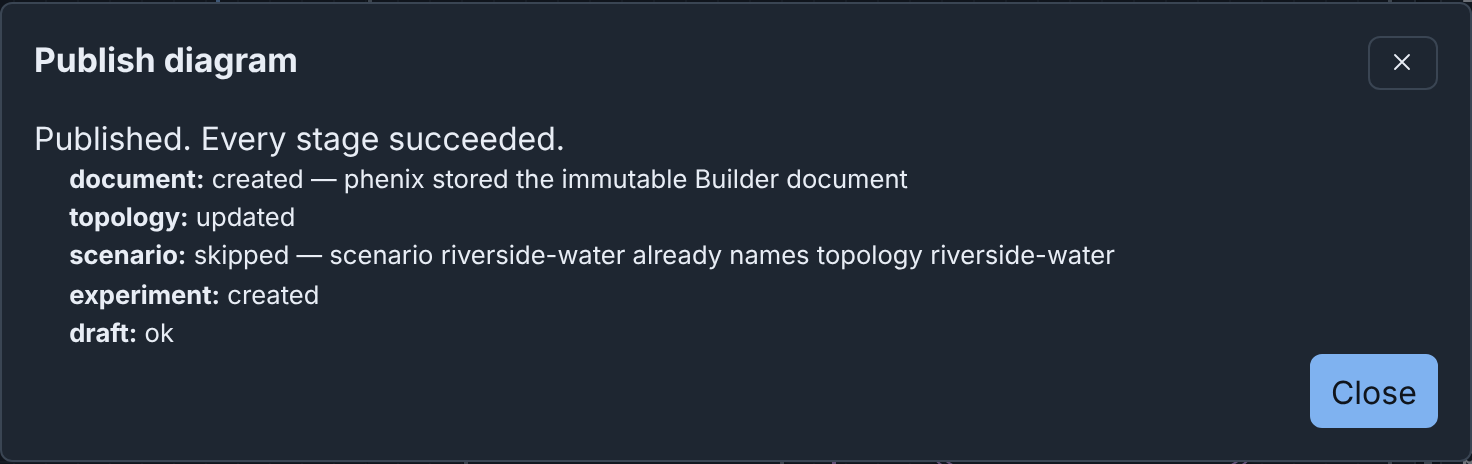
- The dialog says "Published. Every stage succeeded." Click Close.
phēnix keeps no earlier version of a config. Before Builder replaces a config, it always asks. See Publishing.
Step 7: Open the result
- The Topology config
riverside-waternow hasws-03. On the Configs page, its row has the tagbuilder. Click the tag to open the diagram in Builder again. - The experiment
riverside-labis on the Experiments page. In the editor, Exp in the toolbar opens it. To start it, see Experiments. - Publish does not update experiments that you made outside Builder, such
as
riverside.
Step 8: Download a picture
- Click Download in the toolbar.
- Click PNG. The browser saves
riverside-water.png. - Click Close.
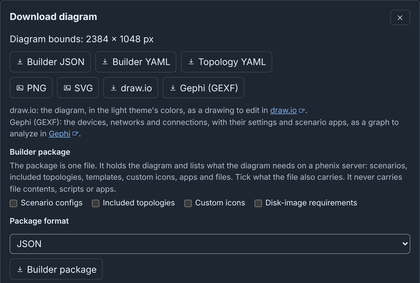
The same dialog saves the diagram as Builder JSON, which Upload opens, or as Topology YAML, the Topology config that Publish would write. To move the diagram to another phēnix server, download a Builder package. See Import, Upload and Download.
Next steps
- Builder saves each later edit to the same draft. To publish the changes, click Publish again with the same names. See Publishing.
- To go back to an earlier version, click Draft History in the toolbar. See Drafts.
- To draw more, see Diagrams. To reuse device settings, see Templates and Icons.
- When something does not work as this page says, see Troubleshooting.